4 Conceptual design
4.3 Conceptual design for human powered flight: a comparison of two design spaces
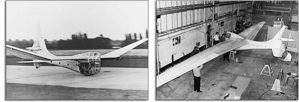
It is possible to become fixed in one particular design solution space and not realise the potential of alternative approaches. Figure 24 shows Puffin, a human-powered aircraft produced by a design team from Hawker Siddeley at Hatfield that was led by an aerodynamicist. The team produced an aerodynamical solution by subordinating all design decisions to the imperative of a clean airflow over the plane, with no bits sticking out in the wind to cause undesirable drag. The aim of the design team was therefore to extract as much lift as possible from the wings, by having the design as aerodynamically perfect as possible (see Aerodynamics). The team even mounted the propeller at the back, so that it would not create any turbulence in the airflow over the wings. The design was made of wood; you can see the detail of the ribs that produce the wing shape and the beam structure inside the wing.
Puffin was built to win the first Kremer prize for human-powered flight. The requirement for winning this prize was to fly a figure-of-eight course around two pylons half a mile apart, with a minimum height of 10 feet at start and finish, using human power alone. The whole of the historical experience of the aircraft industry was available for the designers to draw upon, and it was believed after Puffin's first flight – 1961 – that the prize would soon be won.
Puffin flew well enough in a straight line but did not turn easily and was a nightmare to repair after crashing.
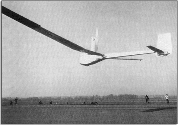
However, a similar approach was taken by all the UK attempts to win this prize. Figure 26 shows the Jupiter, designed by Mr Chris Roper and flown by Flt. Lt. John Potter RAF in 1972. The concept and the wingspan was similar. Jupiter flew a slightly further distance in a straight line, (1171 yards), but was more difficult to turn than Puffin, and no easier to repair.
Aerodynamics
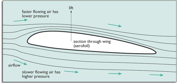
An aircraft generates lift – the force which raises it from the ground – from the shape of its wing. A wing shape is shown in Figure 25. This shape is known as an aerofoil.
Because of the shape of the wing, air flowing past it, as the aircraft moves forward, has to travel further around the top of the wing than along the bottom. It flows faster along the top edge of the wing. This faster flow reduces the pressure at the top, and the pressure difference between the top and bottom of the wing generates the lift. There is a high pressure at the base of the wing pushing against the lower pressure at the upper surface.
Once the force from the lift is greater than the weight of the aircraft, the aircraft can take off.
So, what were the technical issues and why wasn't the design solution effective?
The continuous power available from a fit cyclist is no more than about 400 W, and losses in the transmission and propeller efficiency reduce this to about 250 W. This is not much – about enough to power a couple of powerful lightbulbs.
Aerodynamics tells us that the power, P, needed to fly a plane is:
where M is the total mass of the plane (and pilot) and S is the cross-sectional area of the wing. C is a number within which is wrapped up the basic aerodynamics relating to flight.
To keep the power low this equation tells us to build a light plane with a large wing area: two contradictory requirements. A larger wing will mean more weight.
Once the aerodynamic imperative is accepted, that is C is to be kept small, then the structure that is required to keep a large wing strong enough and stiff enough has to fit inside the wing's aerofoil section. The wing spar acts as a beam in bending. The shape can't be varied much, so the main possibility for design choice lies in materials selection. Steel can't be used because it is too dense; wood is a good, cheap, craft choice. As the wing span of designs increased, exotic materials such as carbon fibre were also used. The wing spans became so large that the wings touched the ground under their own weight until the plane was moving and the wing began to generate lift.
The designs that concentrated on aerodynamics achieved the distance required to win the prize but none of them turned corners at all well. The problem was that the planes flew very close to the ground because climbing would require more power, and the lift from a wing close to the ground is higher than that at altitude due to the ‘ground effect’ (an enhancement to the aerodynamic lift caused by flying close to the ground). However, flying close to the ground poses a problem for an aircraft with limited power. Normally a plane banks (tilts to one side) in order to turn efficiently, but these long wings close to the ground could not bank without driving the inner wing tip into the ground, and there was not enough power available from the pilot to climb in order to gain airspace for manoeuvring. Turning with the wing level is aerodynamically inefficient and the inner wing loses a lot of lift because it is moving relatively slowly through the air.
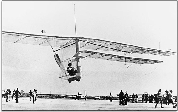
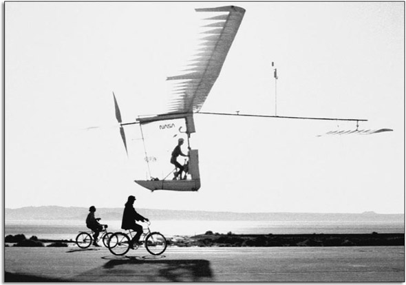
It required an innovation to break out of this aerodynamic solution space which had not achieved the desired result. This was provided by Paul MacCreadey's Gossamer Condor, Figure 27.
We can view this design as occupying a structural, rather than aerodynamic, design space because the design almost ignores the aerodynamic imperative of a low C. A structure designed for minimum mass M looks totally different. This structural design works more like a boat's mast than a beam, with wires in tension and a rod in compression.
The resulting structure was stiff, strong and light and, at the low flying speeds of the plane, the aerodynamic drag carried insufficient penalty to prevent this design winning the Kremer prize of £50 000 in 1977 at an average flying speed of 13 mph.
There was a good deal of pragmatism in the design. The wingspan was 96 feet ‘because the aluminium tube came in 12 foot lengths from the local store’ and Condor's mass was 32 kg (70 lb), which was half that of Puffin with its 93 ft wingspan. There were not a great many formers used to keep the aerofoil shape true along the wing, so when the plane crashed it could be patched up quickly.
According to Paul MacCready, the wing spar broke in flight on only two occasions. On one occasion the damage was caused by turbulence from the wake of a nearby crop-spraying aeroplane. Even with half its wing gone, the Condor flew surprisingly well and was able to land gently. Thanks to the wire bracing, the wing did not fall apart at once.
However, the greatest advantage was that the tension wires, which were so structurally important, could be used to twist the wing when the aircraft manoeuvred. The altered angle of attack along the wing evened out the lift when one wingtip was moving through the air much faster than the other wingtip. So, the plane turned level without too much loss of efficiency. This technique was known in the First World War as wing warping, so the Condor designer could not claim absolute originality, but it was certainly innovative in the context of human-powered flight.
A further prize of £100,000 was offered by the Man-Powered Flight subcommittee of the Royal Aeronautical Society for the first human-powered flight across the English Channel to France. MacCready returned in 1979 and landed that prize with Gossamer Albatross (Figure 28). The aircraft was flown by a racing cyclist, who flew it across the 38 km in 169 minutes, despite an unexpected headwind.
The second Gossamer design was a logical development of the first, with some different materials and a few advertising posters.
Why was Condor so successful? Intuitively, one would think that the best solution would be the one which is aerodynamically best, rather than the one which is most structurally sound.
Using the equation I gave earlier, we can perform a rough calculation to compare the designs of Puffin and Condor.
What we know is:
- Puffin had a mass of 63.5 kg and a wing area of 36 m2.
- Condor had a mass of 34 kg, a wing area of 75 m2 and a pilot mass of 61 kg.
First we notice the success of the structural design solution. Condor has twice the wing area for half the mass. Admittedly the Condor wing is less efficient, but that may be a price worth paying. Let's assume that the same pilot flies both machines (interestingly the aerodynamic designs such as the Puffin were flown by experienced pilots, whereas MacCready chose a racing cyclist). Thus the pilot will be assumed to have a mass of 61 kg in both cases.
Exercise 6
For each of Puffin and Condor, use the formula given above to calculate the power required for them to fly. You will not know C in either case, so just produce a formula of the form, for example
where x is the value of M 3/2/√ S for, in this case, Puffin.
If the two planes are aerodynamic equals, then C will be the same for both. They are not, but aerodynamic improvements at low flying speeds tend to be small percentages so there will not be an enormous difference. The answer from Exercise 6 shows that, if C is similar for each plane, Puffin needs twice the power to fly than Condor. Improvements to the aerodynamics could not generate the extra lift needed to overcome this barrier.




![x [124.6kg]3/2/ 36m2](http://media.kingdown.wilts.sch.uk/pluginfile.php/12027/mod_page/content/1/T173_1_ue017i.jpg)
![x = [124.6]3/2Kg3/2/( 36m2) = 1389kg3/26m = 231.5kg3/2m-1](http://media.kingdown.wilts.sch.uk/pluginfile.php/12027/mod_page/content/1/T173_1_ue018i.jpg)


![M = 34kg (the mass of the plane) + 61kg (the assumed mass of the pilot) = 95kg (S = 75m2- given earlier) x = [95 kg]3/2/ 75 m2= 926kg3/2/ 8.7m= 106.5 kg3/2m-1](http://media.kingdown.wilts.sch.uk/pluginfile.php/12027/mod_page/content/1/T173_1_ue021i.jpg)
