5 Concept to prototype
5.3 Design and innovation 2: the ‘Res-Q-Rail’ stretcher
One of the difficulties with designing is that it is almost always complex. There are contexts, which impose particular constraints on parts of the design and their connections. To describe a design case study, especially for the core stage between concept and prototype, it is necessary to be quite clear about the context in which the design takes place, the stage of definition the design has reached, and finally any requirements of the users and clients which are relevant.
I will describe here a design for a device which is used to transport equipment and casualties to and from the site of railway accidents. A particular difficulty with railways is that they pass through remote areas, with no alternative means of overland access. Fire and ambulance emergency services when called to the scene of an accident may only be able to gain access to the track a mile or so away. These emergency services require a lightweight, portable and compact trolley to take heavy breathing apparatus and cutting equipment to the scene. Casualties on stretchers then need to be transported to waiting ambulances.
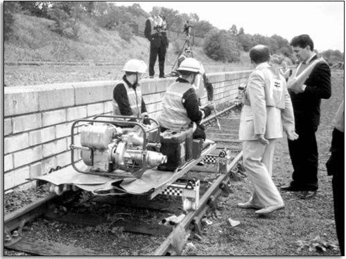
This design started life as a requirement from the emergency services in Northumberland where the railway line to Scotland is inaccessible for long distances. Figure 37 shows an emergency rescue team carrying a stretcher alongside a track in a simulated training accident. Note that six people are needed and progress is hazardous.
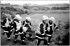
Figure 37: Carrying a stretcher beside a railway track in a simulated training accident. Four people are needed to carry one stretcher plus two to attend to the casualty
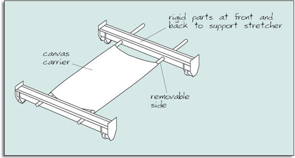
The concept of the ‘stretcher carrier’, as it was called initially, had five modules. These are shown in Figure 38. They consist of:
- two cross pieces (front and back), with wheels, for stretchers to rest on;
- two detachable side pieces joining the front and back;
- a canvas sling between the two sides.
This modular construction allowed the stretcher carrier to be stored compactly, transported to the site easily and assembled quickly.
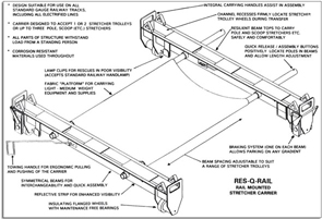
This concept was developed to a prototype in 1994 by designer Rob Davidson. It is patented and in production. The annotated drawing in Figure 39 shows the detailed features in the final design. The annotations explain the reasons for the features introduced when developing the concept.
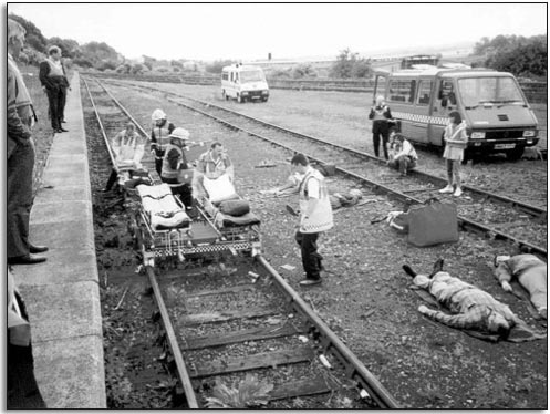
A prototype was built according to the developed concept and tested. Figures 40 and 41 show tests of the final production stretcher carrier now called ‘Res-Q-Rail’. Figure 40 shows tests carrying stretchers and Figure 41 shows tests carrying equipment and people.
I wish to draw your attention to two things. First, the design of the front and back modules uses an aluminium beam fabricated by bending thick sheet. This is strong and lightweight. Second, the wheels are plastic for light weight and low friction. However, nylon, often a good choice where lightness and low friction are needed, is not used. Nylon expands when wet, which might cause the wheels to jam.
The first point – the use of folded aluminium sheet – represents a general design principle of making strong things cheaply, from simple materials. The second point – concerning the material for the wheels – illustrates a specific piece of technical knowledge. There are, of course, a multitude of such guides and constraints on getting to the prototype in this example.
Aluminium was the preferred material as it is both corrosion resistant and lightweight. However, for the carrier, rather than a rigid, flat surface, a sling design is used. This is light and flexible for packing, has a natural dip to hold equipment, and is easily assembled by inserting the side tubes.
After a prototype had been developed, the design was further refined and put into production. However, as with many designs this was not the end of product development. In use, fortunately in training rather than at accidents, a number of new requirements emerged. One was that it was important to keep the carrier stationary, and thus a brake was requested by customers.
Brake concepts were examined by the designer, who decided on a lever design operating by friction onto the track. The key requirement was to transform the vertical motion of a lever (like a car handbrake) to the sides of the carrier and then onto the track. Remember that the wheels are plastic for lightness and corrosion resistance so that it was not feasible to brake onto the wheels as plastics may be easily deformed.
The overall concept of the brake is outlined in Figure 42. The up/down rotation of the brake handle is transferred through a mechanism M to rods L1and L2. These rods act to pull the brake pads P off the track by means of another mechanism N. The ‘natural’ position of the brake handle is on. Positive action (pulling the brake handle up against a spring) is required to pull the brake pads away from contact with the rails. Thus the brake is conceived quite differently from a car handbrake which requires effort to apply the brake. In this case the effort is needed to take off the brake.
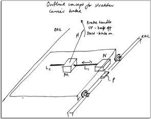
Figure 42: Outline concept for stretcher carrier brake. H is the handle. Pulling up H raises brake pad P against a spring. Releasing H causes P to spring down against rail. Mechanism M converts up/down motion of H to side-to-side movement of L1and L2into up/(L1and L2are link rods). Mechanism N converts motion of links L1and L2down motion of pad P
We will look at one part of this design, namely the mechanism M for converting up/down motion of the brake handle into side-to-side movements of links L1and L2. The spring loading of the brake will be incorporated in the mechanism N. We will only be concerned with the brake handle mechanism M.
The question now is how to realise the concept shown in Figure 42, particularly the mechanism M. Figure 43 shows a sequence of developments for the mechanism M using sketches made by the designer whilst in the process of designing. There are several possible developments, including gears, that were considered by the designer, but we will concentrate on just one of these. This was the preferred route adopted by the designer. Six stages are shown down the left of Figure 43 as a sequence of sketches and drawings made during the design. The first five stages are rough sketches made by the designer and the last stage is a computer aided design model of the detailed design. On the right of Figure 43 are two further sketches relating to the design sequence on the left. Note that these are not enlargements, but further refinements of the design.
Notes are included in each stage indicating how the designer was thinking. Do not be concerned if you cannot read them. These are notes transcribed directly from the designer to show the design ‘in progress’. As these are the designer's sketches and notes there are many things that are not being explained. I use this series of sketches to reveal something about the process used rather than for you to have to achieve a detailed understanding of how the brake works. There are several engineering ‘judgements’ made about tolerances and deformations which are needed to make a design like this work. The designer will only discover whether these are right when prototypes are tested.
Figure 43 (a) shows the brake handle in two possible locations – either pointing forwards or backwards. We may want someone to operate the brake from on the carrier (when transferring equipment and people to the accident scene) or from a position off the carrier (when transporting casualties away from the scene).
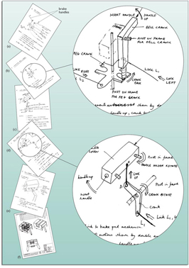
The handle is detachable so that it can be inserted into mechanism M in either the forward or the backward position. The sketch shows a mechanism with two handles, that is with one in the forward and one in the backward position. Remember that only one handle is used at a time.
Look at Figure 43(b), the second sketch in the sequence with its companion drawing and annotations. A ‘bell crank’ is attached to the handle. This crank is pivoted on a fixed frame which will be attached firmly to the front or back cross piece. The fixed frame will probably be in a unit containing the mechanism. This will be attached to the cross members of the stretcher carrier which run between the wheels. The end of the bell crank then moves backwards or forwards in slots in a rotating ‘peg crank’. The rotation then pulls the rods which operate the brake on the track. We are not going to deal with how the brake is brought down on the track. We have quite enough complexity just getting this bit of the design sorted out. Note that the next sketch, Figure 43(c), shows a cable operated solution which was not developed further.
The sketch in Figure 43 (d) is getting close to the final design. All the essential elements are present. Look at the associated drawing. There is a frame for the mechanism which is to be fixed to the stretcher carrier, probably on one of the cross members. There are also two pivots on this frame, one for the brake handle and one for the crank. Compare the two designs in Figures 43(b) and Figure 43(d). They are very different.
The final design is not a sketch. It is an accurate computer-generated picture. At the time of writing (autumn, 2000) this is a current ‘live’ design and a prototype has not been built or tested. Many details still remain, such as a ratchet to keep the brake handle up, the mechanism for raising the pad and spring loading the brake.
The sequence of possible developments of concept in Figure 43 follow a kind of design logic. Changes and transformations of the design do not occur randomly. At each stage the designer considers the current design, looks for opportunities to develop it, perhaps by changing a shape, combining separate components into one, or adding a new feature to meet user requirements. However, the designer is constrained. The design must be easily manufactured and must be very robust (the design will be treated roughly by people in a hurry in difficult conditions).
This is a typical design problem in the engineering industry. There is no space science here. This is an example of designers being creative in meeting a need. It is not a mundane problem. It needs creativity, thought, logic and intelligence to bring such a product to market. We have examined an example which at the time of writing has not been tested. This is intentional, in order for you to catch a glimpse of the middle of the design process without the benefit of hindsight which tends to sanitise the design process as a smooth and ‘logical’ progression from need to concept and prototype. In reality the process is messy and creative as people try to come to terms with a problem and possibilities for its solution. Designing is a complex process, there are guesses, blind alleys, failures and successes. This characterises all stages of design.
SAQ 13
There are many design failures in the things we use every day. We notice these more than the easy-to-use, naturally pleasurable products of good design.
- Identify a simple product or part of a product you think is poorly designed.
- Describe the poor design and give an initial suggestion or concept for improvement. This is not an easy question. Just try and think through the steps. I want you to realise how difficult these questions are and recognise that designing is hard! Do not worry if you cannot complete the answer.
Answer
- (a) Perhaps uncomfortable seats in our car, awkward adjustment and securing of the straps on a bicycle helmet, packaging that is difficult to open, difficult access to buildings and many more.
- (b) For the bicycle helmet the adjustment needs to be secure since the helmet must stay in place. Further difficulty may arise from two loose ends requiring two-handed operation. Perhaps fix one end of securing clip to helmet and incorporate adjustment here?
What SAQ 13 should indicate to you is that problems and poor design do not always stand out clearly. We all get accustomed to using designs which are far from ideal. We all adapt. We have to think about possible solutions to realise the extent of design shortcomings. In a curious sense design-minded people are evaluating all the time; they are continually exploring what might be. Good designers see new (and possibly better) ways; poor designers put up with old ways. So you could say that all design is innovation. I will come back to this theme towards the end of the unit.
The next stage of design takes a prototype, probably a rather rushed and incomplete affair, and submits it to testing so that its performance can be evaluated. As a result modifications are made and the final design delivered to market. This is the subject of the next section, which describes a case study of taking a design to market.