1 Design and designing
1.4 Designing as model-making and model-using
Any attempt to integrate skills, knowledge, abilities and sensitivities in formulating a design is going to be difficult, and the outcome from one designer's work is likely to differ from another person's attempt. Differences might occur in the unravelling or interpretation of various problems, the generation of ideas intended to overcome these problems or the quality of communication provided to convince others of the quality of your work. Figure 1 showed various designs for a telephone. Differences might not only arise in the form of the product, though. There may also be differences in the physical or scientific principles that different designs exploit. Figure 2, for example, shows a conventional light bulb and a light-emitting diode, both of which emit light but using completely different physical processes.
In formulating a design, designers use their mental and physical tools for a process which has been termed modelling. Models and modelling encompass a wide range of applications. You may be most familiar with its use to describe a new car (as in ‘the latest model’) or as a title for those men and women who display the latest fashion creations (fashion models). These popular uses of the term have some things in common with the way designers use it but their meanings have a number of levels which I want to explore here.
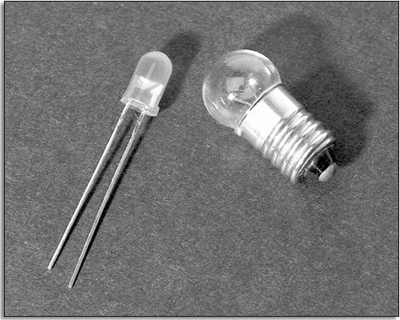
Figure 2: A conventional light bulb, which works by heating of a tungsten filament, and a light-emitting diode (LED), which works by light emitted from a semiconducting junction
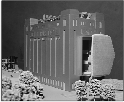
You will probably be familiar with the use of the term model to describe constructions such as an architect's scale model of a proposed building, or a bigger-than-life-size model of a new toothbrush used in a shop display. These are three-dimensional models. I would also use the term ‘model’ to describe drawings and sketches; in this case they are simply two-dimensional models. An important distinction in the use of such models might become immediately obvious to you, namely their function. That is, the primary function for some models is the communication of information, whereas for others it is to act as an aid in exploring and developing ideas. An architect's scale model (Figure 3) which has details of the finished structure, and might incorporate windows, walkways and figures to the appropriate scale, is likely to have been made at the end of the design process, or at least at the end of one design stage. Its primary aim would be to communicate detail to others involved in the process, and this might be achieved using photographs of the scale model.
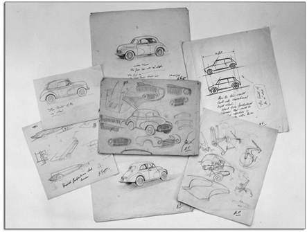
Models in the form of drawings might have a number of purposes. At one extreme, engineering drawings are supposed to facilitate unambiguous communication of precise intention. Sketches, on the other hand, are models which have a primary function to assist an individual designer or design team to creatively resolve problems. Few sketches are formally presented in the way the scale model might be. They are often rough, incomplete and ambiguous (Figure 4). In as much as they are ‘representations’ of thought or intention they can assist communication but it is their rough ambiguity which assists creativity.
Models might also be expressed as scientific formulae which include the important physical characteristics of the product. So it might, for example, be possible to determine the stresses under load on the gears in a gearbox by a formula including loads, tooth profile and material properties. A computer model of a gearbox might just encode the mathematical formulae but it might also be used to simulate performance where simple formulae do not apply. Computer models might thus take the form of graphic images or, alternatively highly specified virtual forms.
Another type of model might be those mental pictures we create when we are thinking about a problem or about ways of solving it. We could call this cognitive modelling. (‘Cognitive’ here indicates that this process involves knowledge, experience and reasoning, as well as perception, aesthetics and instinct.)

I could take this one stage further. Consider the skill of designing as, in part, a skill with modelling. Being able to design would imply an ability to link cognitive modelling with various physical modelling tools which might include making cardboard or wooden forms, sketching on paper, constructing plans and elevations as engineering drawings, using engineering formulae, generating computer models, and making electronic circuits on ‘breadboards’ (temporary circuit boards used for prototyping). As you can see, the design process is a microcosm of the process of engineering.
An ability to make and use models is vital to designing. Models assist in the generation, testing, evaluation, communication and selling of ideas and, as such, their use is not limited to designers. Some modelling techniques are particularly good at supporting several functions at once. For example, some models might be so quick to construct that they can help in the creative generation of ideas. They might also be accurate enough to be used to share ideas with other people involved in the process. The fast sketch drawings created by designer Ian Callum at the conceptual stage of the Aston Martin V12 Vanquish (Figure 6(a)) would be a good case in point: such sketches can be assessed for potential appeal in the market before technical questions such as engine power or ignition circuitry are raised (see Ian Callum and the V12 Vanquish).
Of course, not all designers are competent with all modelling techniques. Very often designers will specialise. However, a competence at modelling is characteristic of a competence at designing. Engineering design usually involves a lot of modelling, and a lot of it is done on computer. For example, the mechanical parts of a new car or engine are usually modelled in a CAD (computer-aided design) system using a technique called finite element analysis.
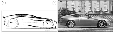
Figure 6: (a) Sketch drawing used at the conceptual stage of the Aston Martin V12 Vanquish (b) The finished vehicle
Ian Callum and the V12 Vanquish
Designer Ian Callum, originally from Dumfries in Scotland, studied at the Glasgow School of Art and at the Royal College of Art in London. Early work for Ford led to appointments in Britain, Japan, USA, Australia and Italy, among other countries. Since 1990 he has been commissioned to design for several manufacturers, including Mazda, Range Rover, Volvo, Nissan and Aston Martin.
For Aston Martin, Callum designed the DB7 model (unveiled in 1993). He then designed the concept for the V12 Vanquish (Figure 6). This concept was unveiled at various motor shows during 1998, and its favourable reception led Aston Martin to decide to put the model into production as soon as possible.
The main body of the V12 Vanquish is formed from extruded aluminium sections, bonded and riveted around a central transmission tunnel made from carbon fibre. At the front of the vehicle, a steel, aluminium and carbon fibre subframe carries the engine, transmission and front suspension. Engine control, transmission and braking all make extensive use of microelectronics.
The Aston Martin V12 Vanquish was launched in 2001, and is made at the Aston Martin plant in Newport Pagnell, Buckinghamshire. Each car is hand built, although computer-controlled processes are used for the composite sections.
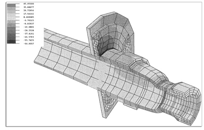
Figure 7: Indy racing car rear-wheel hub and section of wheel during cornering, modelled by finite element analysis. The original image uses colour to show regions of stress, as classified in the key alongside the image. The highest compressive stress is in the dark region above the hub
These systems can predict the physical behaviour of the object, including points where it is highly stressed (Figure 7).
The next section returns to the issue of needs, the exploration of which also involves the exploitation of modelling.